Project Pete
Phase Controlled Clutch Arrangement
Background
My first graduate job was at QinetiQ where I worked as a design engineer on a large series hybrid electric transmission where all of the traction power came from electric motors. Specifically I was involved with specifying the gear change system including the components and the control algorithms. The system was designed by a really excellent engineer who I learned a great deal from and who was the technical expert in the winning team in an episode of scrapheap challenge (see here).
Electric transmissions have fantastic efficiency and low speed torque characteristics compared to conventional engines. Often you can get away with no gear stages whatsoever in the case of direct drives. In many cases however you find it is useful to have some gearing to help optimise the drivetrain (in spite of the efficiency penalty imposed by the gear mesh). If you don't have any gears, you tend to find permanent magnet machines end up running too fast when the vehicle is at full speed. This means you need an ever increasing voltage to continue providing current for more torque, things get to the point where you need to start 'field weakening' which means advancing the phase of the power applied to the AC motor so that you are energising the coils when the rotating magnetic field from the rotor is at a lower flux. This allows you to go faster however you need proportionally more current per unit power (albeit at a reduced voltage), this reduces the 'power factor' of the motor and increases the losses in the windings making the motor less efficient and at times very hot!
Introducing gears into an electric drivetrain introduces a new challenge... torque transients. Changing gears in a conventional petrol car is quite straightforward due to the relatively low inertia of a regular internal combustion engine. Many permanent magnet electric motors have a much higher inertia and if you engage the driveline to the motor with an appreciable speed miss-match you can get some serious torque spikes.
In 2013 I ran Oxford's technical team and their entry vehicle to the Shell Ecomarathon. We had an electric drivetrain which had to be as light as possible and this led to the selection of a small Maxon PM motor and a single high ratio gear stage. We didn't have the luxury of a wet lubrication system and so ended up with a very interesting material selection for the gears which ended up being a phosphor bronze main gear coupled to a cast iron pinion. It turns out that cast iron is an excellent dry gear material since it flakes graphite which is a good solid lubricant. These two materials are also very stiff meaning that we had a combination of low hysteresis losses and low friction without needing any transmission oil.
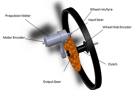
Isometric view of the drivetrain assembly which operated on the rear wheel assembly (which also steered about the centre of the wheel hub
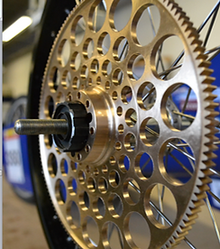
Phosphor bronze main gear which was paired with a cast iron input pinion achieving high mesh stiffness and low mesh friction
The two figures above show the layout of the drive-train as designed for our 2013 competition entry along with a photograph of the phosphor bronze gear which looked pretty sick!
Whilst this was a fixed gear arrangement, to avoid power losses we did want to be able to disengage the drivetrain whenever the vehicle was coasting. These losses occur due to a combination of friction in the gears and motor alongside magnetic losses in the motor which continue even if you switch the power off because of the permanent magnets which maintain a rotating field (imagine an induction cooker which you can't switch off). I designed a gear change arrangement which comprised of an actuator, some torsion springs and used an adapted bike hub. However, when doing some calculations, I realised that the torque transient would likely break a gear tooth (a catastrophic thing to happen).
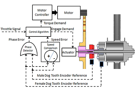
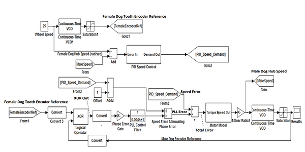
We needed a way to synchronise the speed of the motor drive with the speed of the gear train before engaging the drive. More than that, we also needed to align the phase of a set of dog clutches. To do this, I came up with the system diagram below which used hall sensors on the dog clutches and wheel hub so that we measure when an engagement was feasible.

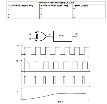
The challenge was to come up with a robust control scheme which would quickly achieve both speed and phase control of the propulsion motor so that we could rapidly align the clutches before engagement. Back when I was an undergraduate student, I had studied phase lock loops which are used extensively in digital electronics. I was exploring their application to an optical clocking arrangement for microprocessors (but that's another story!). I got really interested in phase lock loops and the control arrangements around them. They're used every time you want to synchronise two digital systems to each other. An exclusive OR gate records the input from the two oscillators you wish to synchronise and the output is proportional to the phase error between them. If you filter this phase error you can produce a control signal which speeds up or slow downs the oscillator you wish to synchronise. The two diagrams below show the truth table for an exclusive OR gate and how filtering its output in the presence of two oscillators gives you the phase error. I've also shown the MATLAB layout of the control scheme which would align the clutches.
System diagram implementing phase control of drivetrain (shown in section view)
Finite Element Stress analysis conducted by Rob Richardson on main gear wheel
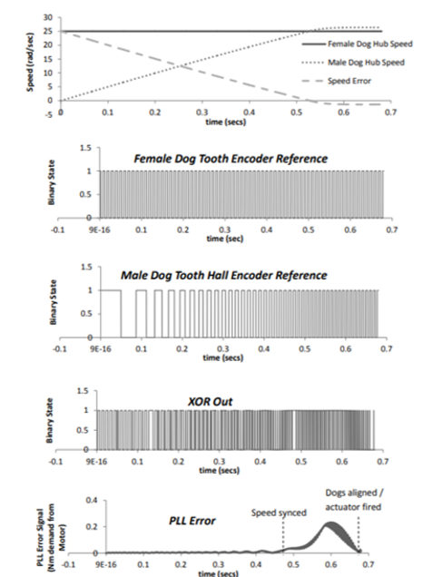
The control system was able to record the speed and phase difference and then take over the motor speed to align the clutches prior to engagement. We simulated this numerically with the output shown below.
Synthesising phase error between two oscillators using an XOR gate
Control diagram implemented in MATLAB Simulink to control clutches
We built the drivetrain with the actuators and put in some torsion springs to allow for control hiccups. The assembly worked well however was quite challenging for our driver Lucy to operate, she had to master the skill of putting the vehicle into coast, waiting for the gears to align and powering up again which was quite clumsy! I like to think that with more time we would have got things operating more slickly. However Lucy did an excellent job and beat our previous year's energy consumption figure by about 30%.
The design earned us the Technical Innovation Award at the 2013 Shell Ecomarathon. The video below was produced by Rob Richardson, a mechanical engineer on the team who undertook detailed simulation of the stresses in the gear.
System response during engagement of geartrain
Our trip to Rotterdam and experience at the 2013 Shell Ecomarathon
Concluding thoughts
Whilst we never had a chance to fully refine the system above, we certainly discovered that reducing coasting losses in electric vehicles was a worthwhile thing to do (see following paper here for more information). I'm not sure whether production electric vehicles nowadays deploy active coasting strategies to reduce energy consumption and would be interested to hear from anyone working in this space to find out. I should also say that coasting losses will inevitably be lower for non-pm machines like induction or switched reluctance motors, however even with these systems, the losses associated with a gear train, not to mention the high windage losses in a small magnetic air-gap, would undoubtedly remain significant.