Project Pete
Reconfigurable PV Array
Background
Back in 2013, I was involved with a technical team tasked with entering that year's Shell Eco Marathon (an electric car endurance competition).
Our entry was a solar electric vehicle comprising: a single monocoque carbon fibre shell, rear wheel drive and steering assembly along with a small lithium battery pack. There were a number of interesting features to the vehicle which you can read in more detail about here but in particular, one key idea that we tried out was the 'reconfigurable PV array'.
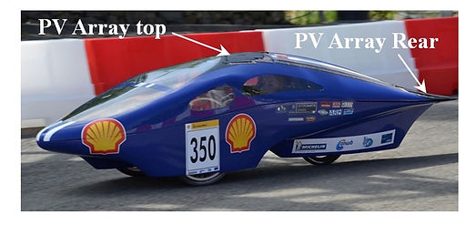
Figure 1 Electric car at 2013 Eco Marathon
There were many (annoying!) design constraints imposed on the vehicle, one of which was that we were only allowed up to 1 tea towel's worth of solar array area. After being turned down for free mono crystalline cells from a US Satellite company we ended up getting sponsored by IXYS who kindly donated 130 high grade PV modules. This filled our tea towel but also gave us the opportunity to configure the array between two configurations... (the plot thickens)
The Reconfigurable PV Array
The basic idea was to dynamically change the connections within the solar array so that we could move the maximum power point (MPP) of the array's I-V curve to be as close as possible to the operating voltage of the car's propulsion battery. During the race, the battery voltage would drop considerably (being as small as possible to save weight), consequently the power electronics had to bridge an increasing divide which would ultimately compromise the system's efficiency. By flipping between a 10X13 to a 13X10 (Series X Parallel) array, we could move the MPP voltage closer to the battery terminals and maintain high efficiency. We wrote a short conference paper on the scheme which you can read here.
The best way to explain this is with the following two graphs. Figure 2 shows the I-V curve for both array configurations whilst the Figure 3 shows a typical efficiency curve for a DC-DC buck converter:


Figure 2 I-V and power characteristics of array
Figure 3 DC-DC Converter Efficiency
The IV Curves for both array configurations (Figure 3) were set-up so that the MPP voltage points overlapped with the range of the battery voltage encountered during each race. The right hand graph shows how the efficiency associated with the power electronics dropped off as the difference between the PV array voltage and the battery grows (resulting in a lowering duty cycle). By flipping the arrays, we could keep the duty cycle high at all times or even allow us to bypass the DC-DC converter altogether. The following two diagrams try to explain this better!:


Figure 4 System output in 13X10 mode
Figure 5 System output in 10X13 mode
Building the array was quite a feat of design and soldering! The task was ably accomplished by Richard Wong and Ren Kang (Ren's also a co-founder with me at Mixergy). Figure 6 shows them on a sunny day testing the array when something went wrong!
Indeed there were many things to go wrong as we relied on a bank of a dozen or so MOSFETs to switch between the two array states. This was all strung together on bits of breadboard which made things pretty temperamental.
Before testing the system, we simulated how we thought it would behave and presented the results in (this paper). We ran many simulations in LT-Spice to derive the overall efficiency map which would determine how it ought to work (Figure 7):


Figure 6 Richard and Ren fixing the system
Figure 7 System peak operational efficiency map
These numerical results indicated that we might theoretically achieve an average efficiency improvement of 12% and a peak improvement of 20%. This was however very much an educated guess at best as our simulation glossed over many factors that we couldn't really capture such as the effect of partial shading over the array along with the real I-V characteristics of the whole panel rather than a model of it. Luckily, upstairs in our building there was a lab working on organic solar cells. Whilst these would be no good for a car (though mouldy slime might induce a turbulent boundary layer), it did mean that we could get our hands on a black-body radiation source (or miniature sun in a box) which we could experiment with. Figures 8 and 9 show our experimental set-up and the arrangement of equipment we used.

Figure 8 Lab experiment with black body source

Figure 9 Schematic layout
How well did it work?..
Our final results indicated an average efficiency improvement of 17% with a low of 3% and a high of 29%. This was an encouraging result however there are a number of caveats that are important to consider:
1. We probably weren't using the most well designed buck converter (though we tried to get the most efficient arrangement possible (i.e low voltage drop free-wheel diodes and transistors etc), we weren't in a position to consider more advanced topologies such as adaptive resonant converters. However, these more sophisticated schemes still remain rare in practice and limited to pretty narrow operating parameters so I'm not sure these would have performed better.
2. The experiments were conducted with the radiation source pointing directly at the roof of the car whereas in reality the solar angles would've been all over the place resulting in partial shading which could have uniquely compromised the system.
3. We never had a chance to conduct controlled experiments when the system finally got integrated into the vehicle, all we know is that it worked well, reducing our power consumption by about 20% relative to the previous year's entry
Concluding thoughts...
Whilst this felt like a very cool idea at the time (and did seem to work quite well), I'm not sure it would find wider commercial significance aside from fairly niche applications justifying the engineering overhead. I think the theme of adaptive solar panels is an interesting one that goes beyond simply improving the efficiency of power electronics. For instance, where you have flexible PV panels that contort around complicated shapes, having multiple regions which are switchable could be useful in overcoming issues around partial shading without the losses associated with blocking diodes.
Setting all the technical stuff aside, it was a great experience with Richard and Ren alongside all the other technical shenanigans associated with the Shell Eco-Marathon.